

You may download a copy of this synopsis as of April 24, 1998, in Portable Document Format (PDF) for reading and printing with such tools as Adobe Acrobat or Ghostscript. A ZIP archive of all the PDF synopses as of April 24, 1998, is also available.
Adobe Acrobat is available without fee from Adobe, Inc. Ghostscript is free software and is available from the University of Wisconsin.
Warning: This HTML file may contain markup errors and/or missing symbols, and is probably not the final version. See the PDF file for a more accurate representation.
Disclaimer: Opinions expressed in the following synopsis are those of the author and are not necessarily those of the US Department of Energy or T. Dan Bracken, Inc.
Field management minimizes the impact that magnetic or electric fields have on their surroundings. It may be necessary to reduce electric- or magnetic-field interference or to allay public or employee concern. The management of magnetic or electric fields may involve the following:
or a combination of these methods.
A variety of field-management techniques has been developed so that they are available for use should they be needed to reduce fields [1,2,3,4,5,6,7,8,9]. Management of electric fields, when required, is easily accomplished through material shielding. Management of magnetic fields can be more difficult because they are not effectively shielded by many materials.
Figure 1 provides insight to several field-management strategies. It provides the magnetic-field equations for four different wire configurations. The first is a single current-carrying wire. The second is an example of lines carrying equal but opposite currents, such as the wiring in a residence. The third example has the current in one of the conductors split and positioned on either side of the other conductor. The fourth wiring example is a current loop similar to the current flow that might be found in many common appliances.
Five methods of field management can be found in Figure 1.
A sixth field-management option is to reduce the field in selected areas (shielding) by use of conducting materials, which cancel the field through induced eddy currents, or by flux-shunting materials that redirect the magnetic field. Essentially all field-management strategies make use of one or more of these techniques.
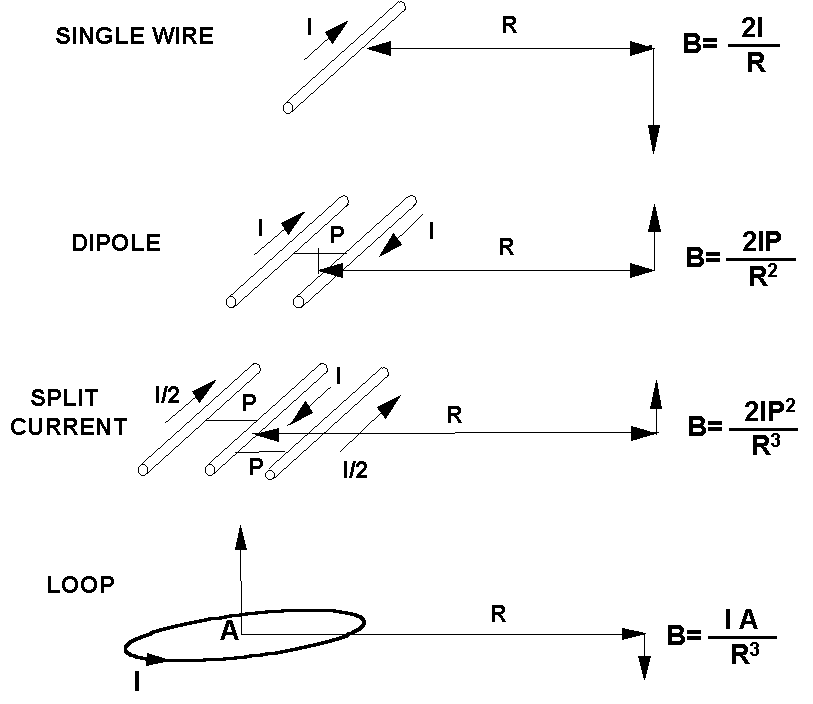
Figure 1. Magnetic-field equations for four different wire configurations. I is in Amperes; A is in square meters; R is in meters; and B is in milligauss.
Distance from magnetic-field sources can be obtained by rearranging a site, such as an office or room in a home, so that areas with higher magnetic fields are less frequented. In some cases, the magnetic-field sources can be relocated to increase the distance.
The magnetic field can be reduced by decreasing the current in a source. For transmission and distribution lines, one method for reducing the current is to increase the voltage. This will decrease the current for the same amount of power transfer (Power = Voltage x Current = 2 Voltage x 1/2 Current).
Ideally, the net current (vector sum of currents) on a set of conductors is zero; however, this is not always the case where there are multiple grounding paths in the power distribution system, as illustrated in Figure 2. Current may return to a transformer through both the service neutral and multiple neighborhood grounding paths [10,11]. Overall improvement of the power-system neutral and its connections, dielectric couplers in the water system, or Net Current Control Devices on service conductors (Figure 3) [12,13] can reduce the stray grounding current and its resulting magnetic field.
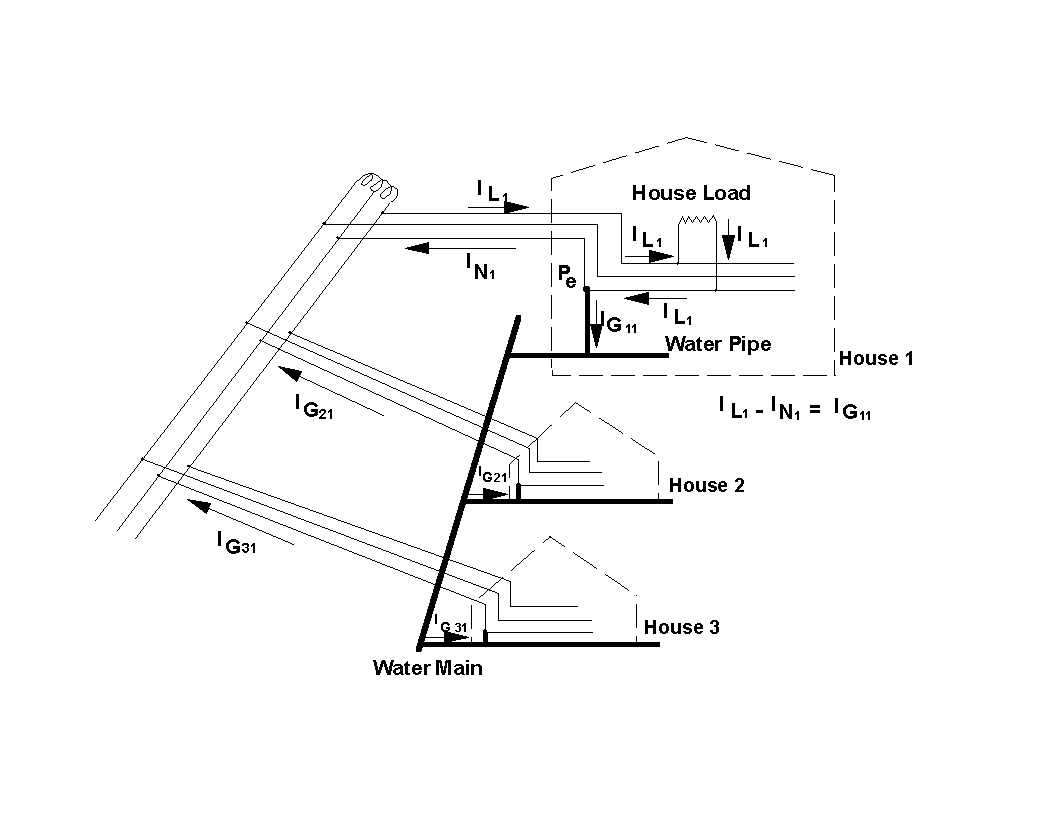
Figure 2. Multiple grounding paths in a residential neighborhood.
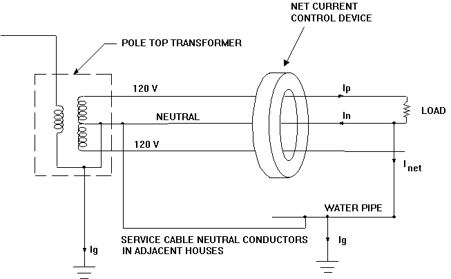
Figure 3. Net Current Control device inductively couples the neutral and voltage conductors together, encouraging current to return on the neutral instead of on alternative ground paths.
Currents can be reduced by improving the power efficiency of devices. Devices at higher operating voltages will also decrease their current use for the same power usage.
Design changes can reduce the magnetic field of sources. This is usually accomplished by decreasing the distance between conductors - for instance, decreasing the loop size in appliances to provide better cancellation of the currents. Figure 4 provides an example of this for an electric range element [14].
Reducing the phase spacing of power lines, known as compaction, can lower their magnetic fields. Figure 5 illustrates the midspan compaction of an existing line using interphase insulators [15]. Not only is the phase spacing of the line reduced, but also the ground clearance of the two outer phases is increased. The use of interphase spacers may not be appropriate for all lines due to concerns with structural loading, line tensioning, or corona performance.
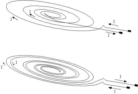
Figure 4. Example of a low-field electric range element compared to a typical electric-range element. In the low-field range element, the current returns along the same path, minimizing the current loop size.

Figure 5. Compaction of the midspan of an existing line using interphase insulators without changing the line structures.
Other power-line design changes that can reduce the magnetic field include phase arrangement on multiple-line corridors and phase splitting. The current phasing of multiple power lines on the same tower or corridor can be arranged to provide some cancellation of the currents and thus lower fields.
Phase currents of power lines can also be split and placed, as illustrated in Figure 6 for two split-phase line designs to further reduce the magnetic field [15]. This provides even better cancellation of the currents than for a compact line so that the magnetic fields decrease with the cube of the distance instead of just the square of the distance. Figure 7 compares the magnetic-field profile of a compact vertical split-phase 115-kV line to the field profile of a conventional 115-kV line with a flat configuration.
Compaction and phase-current splitting are effective only the line has essentially no net current and the currents are well-balanced. This is usually the case for higher-voltage transmission lines, but it is not necessarily true for distribution lines and for some lower-voltage transmission lines [16].
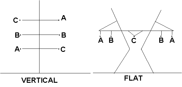
Figure 6. Two split-phase line designs.
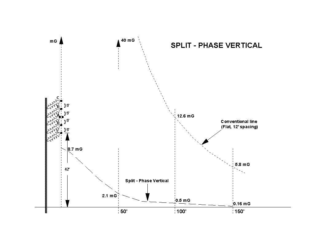
Figure 7. Example of a compact vertical 115-kV low-field split-phase line. The magnetic-field profile is compared to the magnetic-field profile of a conventional flat 115-kV line with a 12-ft. phase spacing.
Low-field line design options are discussed in several references [1,2,7,8,9,15].
Loops of current can be placed to reduce or cancel the magnetic field in specific areas such as rooms with equipment sensitive to interference from magnetic fields. The current in the loops can be either actively driven (active loops) or passively induced by existing fields (passive loops). A discussion of field cancellation with loops is provided in Reference 3.
Active loops generally have a magnetic-field sensing coil located in the field of interest. The signal from the sensing coil provides feedback to control the amount of current driven in the loop. [17]. The active loop is located such that its magnetic field reduces or cancels the existing magnetic field.
Active loops can consist of multiple-turn coils with small conductors, because the current is actively driven in the loops. The actively driven current can also contain harmonics of the power frequency, if necessary, to reduce or cancel harmonics in the existing magnetic field. An active loop can be a multiple-frequency device, but it does require external power.
Like active loops, passive loops are oriented so that their field will reduce the existing magnetic field. Current is induced in passive loops, however, by the existing field. Passive loops usually consist of single large conductors to minimize impedance. A capacitor is often used to tune the loop in order to increase the induced current in the loop. Since the current is passively induced, low overall impedance of the loop is critical. Resistance of the conductor, connection resistances, and internal capacitor resistance must be kept at a minimum and accounted for to allow tuning of the loop for maximum performance.
Passive loops are self-regulating, coupled directly to the external field, and require no external power. Passive loops are optimized for peak field-cancellation performance at a specific frequency (usually the power frequency) [18,19]. They are essentially single-frequency devices. If harmonics are present, multiple loops tuned to specific harmonic frequencies are required.
Material Shielding
Field management can also be achieved through use of material shielding. Material shielding of ac magnetic fields uses either conductive material or ferromagnetic material. To be more effective, material shields should enclose either the magnetic-field source or the area to be shielded, as illustrated in Figure 8. Connections between sections of shielding material should be securely joined by soldering or welding [6,20].
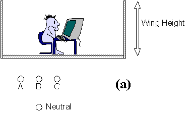
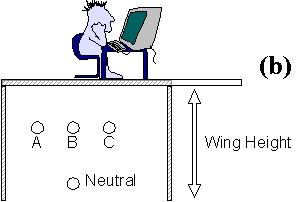
Figure 8. To minimize fringing of the magnetic field around the edges of the shield, the material shield should essentially enclose either the field source (a) or the area to be shielded (b). This can be accomplished by extending the shield material down past the source or up past the area to be shielded.
Conductive material acts as a shield because induced eddy currents produce a magnetic field that opposes the existing magnetic field. A conductive sheet is similar to an infinite number of microscopic passive loops. The field perpendicular to the conductive sheet induces the eddy currents. Thus, a conductive sheet is most effective in shielding magnetic fields perpendicular to its surface. It has little effect on fields parallel to its surface [1,6,21,22].
Ferromagnetic material shields by redirecting the magnetic field. Ferromagnetic materials, such as iron or steel, shunt the magnetic flux past an area, essentially providing a short cut between two points, or short circuit, for the magnetic field. It is most effective shunting flux that is parallel to its surface; it has little effect on the magnetic field perpendicular to its surface. An effective flux-shunting material is one with a high permeability. Iron and steel have high permeabilities, but some alloysūsuch as mu-metal, a mix of nickel, iron, copper and chromiumūhave even higher permeabilities. Iron and nickel alloys have higher permeabilities than just iron or steel but are more expensive and can be difficult to handle [6,21].
Some materials provide both flux-shunting and conductive-eddy current shielding. Iron and steel are both flux-shunting and conductive materials. They can provide flux-shunting at dc and low frequencies and conductive-eddy current shielding at higher frequencies. The geometry of source and shield interacts with these materials in a complex way. Changing the source - shield distance may produce poorer shielding at low frequencies, but better shielding at higher frequencies. An effective method of providing both conductive and flux-shunting shielding is to use layered conductive and high-permeability materials, such as an aluminum-steel sandwich. An aluminum-steel sandwich can often provide better shielding than a single material layer of similar thickness [1,6,20,23,24].
RAPID Engineering Project #8 considered six distinct sources of magnetic field. They are:
Each source presented a unique set of limitations and possibilities for field-management options. The effectiveness, cost, environmental impact, and safety concerns of the field management options were considered for each of the six source situations [1].
Magnetic-field management techniques of line compaction, phase-splitting, voltage upgrading, underground pipe-type cables, and passive cancellation loops were evaluated. A 500-kV or 765-kV option could not be identified to meet 50- to 100-mG field levels on the right-of-way. A passive loop might be an effective method to keep the field levels below 50 mG at the edge of the right-of-way. Costs for a 345-kV line could triple or quadruple to meet a 20-mG level and increase by as much as 50% for lower-voltage lines. Underground pipe-type cables would likely be needed to reach a 2-mG level, but they are not commercially available for voltages exceeding 345 kV [1].
Magnetic-field management techniques of line compaction, phase-splitting, voltage upgrading, and net-current control were evaluated for balanced phase-current conditions. Significant cost increases were seen, using field levels of 5 mG or less. Costs increased up to 40% for 13.2-kV line designs, and 50% to 100% for 34.5-kV lines in order to reach a 2-mG level. Heavily loaded distribution circuits would likely require underground conduit to reach a 2-mG level.
If 2-5-mG levels were set as targets, control of zero sequence current (net current) would be necessary at every point on the distribution system. This would require major changes in line design, grounding methods, distribution-voltage selection, and transformer sizing [1].
Most of the magnetic field at a substation perimeter is due to entering and exiting transmission and distribution lines. Costs and limitations would be similar to those listed for transmission and distribution lines. A low-field substation might require expanding the perimeter fence. Methods for reducing the fields in the substations encountered by workers include shielding of metal-clad switchgear and gas-insulated buses [1].
A variety of resident/utility customer-owned power-distribution equipment exists: for instance, transformers, switchgear, buses, service panels, and general wiring. Grounding beyond the service panel can be a significant field source if alternate return-current paths are created.
Field management includes rewiring to correct stray return-current loops, installing net-current control devices (Figure 3), use of metal conduit, and material shielding of buses, feeders, and transformer vaults. A 5-mG target level could double the installation cost of vaults, buses, and feeders. Some office buildings have already had to retrofit magnetic-field shielding to reduce computer-display interference [1].
The primary sources of magnetic fields in end-user devices are resistive heating elements, motors, transformers, power cords, and general wiring. Field-management options for these include use of adjacent return (Figure 4) or bifiliar heating elements, replacement of inexpensive motors with more expensive heavier-duty motors, use of torodial transformers, compaction of wiring, and installation of shielding for most sources. Some industrial-welding and electrically heated metal-melting processes would present extraordinary costs and design challenges to meet low-field limits [1].
Power and low-frequency magnetic-field limits would affect electric transportation systems such as railways. Field limits within the transportation right-of-way would be difficult to meet, given the design of the system. Field-management techniques might include dual overhead bus-type feed systems, use of higher voltages, and shielding [1].
A variety of field-management strategies has been developed for use if needed. Some of these management techniques for magnetic field have been used to reduce interference with equipment, such as PC monitors, or to allay public or employee concern. Field management can be accomplished through separation, source modification, or shielding with loops or material. The cost of field management depends strongly on the magnetic-field source and the target field criteria. Field management becomes much more costly and complex when source modification or shielding become necessary. Electric-field management is seldom a concern, and can be accomplished with simple shielding.
Key Questions